
Members Area Tutorial: Create an Advanced 3D Matte Painting Using Sketchup and Photoshop (Part 1)
This tutorial is a mammoth, and actually our longest, most in depth tutorial on record! It’s great to welcome Caroline to the team, and I’m sure you guys will learn a lot from her.
This tutorial was simply too long to post as a single post, with around 200 images and 57 incredibly detailed steps. As a result we have split it into two sections. Today’s section (Part 1) teaches you how to construct a complex building structure from scratch using the free software Google Sketchup. Part 2 will be posted this Friday and shows you how to take the 3D Sketchup model and use advanced matte painting techniques and advanced Photoshop skills to turn it into a realistic final scene.
Let’s get going!
A note from Caroline:
In this tutorial you’ll find out how to use a “sketch” created in a 3D application as the foundation for a matte painting. To create the 3D template we’ll use a nifty little program called Sketchup. Most 3D programs have a very steep learning curve but Sketchup, which was designed with 2D artists in mind, can easily be learned in as little as an hour or two. Best of all, Sketchup is free!
After we’ve created the 3D sketch, we’ll take it into Photoshop and turn it into a matte painting using photo manipulation techniques and some simple brush work.
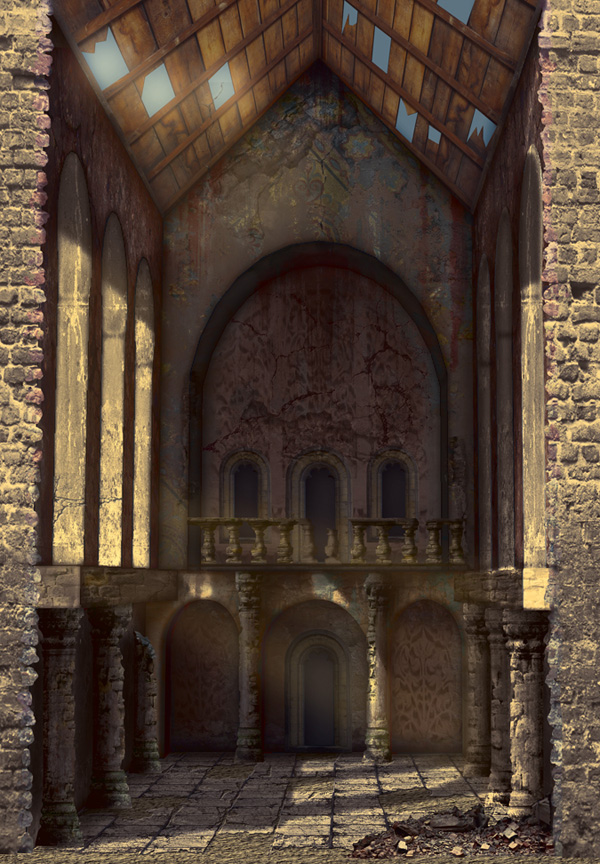
Final Image
As always, this is the final image that we’ll be creating:
Resources Used In This Tutorial
- Sketch Up (Download Here)
- Sketch Up Tutorials
- Plaster 1 (Download Original)
- Plaster 2 (Download Larger)
- Plaster 3 (Download Original)
- Plaster 4 (Download Larger)
- Wood (Free Account Required for Download)
- Floor Tiles (Free Account Required for Download)
- Brick (Download Larger)
- Carving (Free Account Required for Download)
- Mural (Free Account Required for Download)
- Pillar (Free Account Required for Download)
- Window (Free Account Required for Download)
- Balustrade (Free Account Required for Download)
- Soil (Free Account Required for Download)
- Damage 1 (Download Larger)
- Damage 2 (by Race Eend)
- Damage 3 (Free Account Required for Download)
- Damage 4 (Free Account Required for Download)
- Rubble (Download Original)
- Brushes (by Logical Mess)
- Swatches (by Logical Mess)
Step 1
When you start Sketchup, you’ll see the start up screen. First of all, and this is optional, you might want to print the Quick Reference Card. It’s very handy to have close by, especially when you’ve never used Sketchup before.
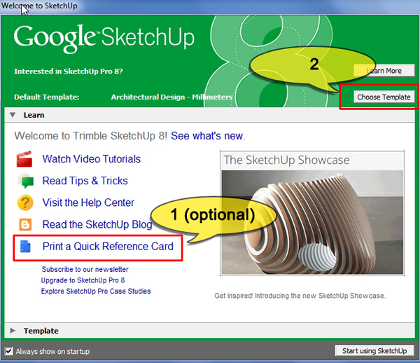
Next, click the Choose Template button and pick “Architectural Design – Millimeters” from the list. To create a new file using this template, click the “Start using Sketchup” button at the bottom of the dialog.

Step 2
When the main screen appears, choose View > Toolbars from the menu and activate the toolbars we need as shown below.

Step 3
We’re now ready to start creating the structure.
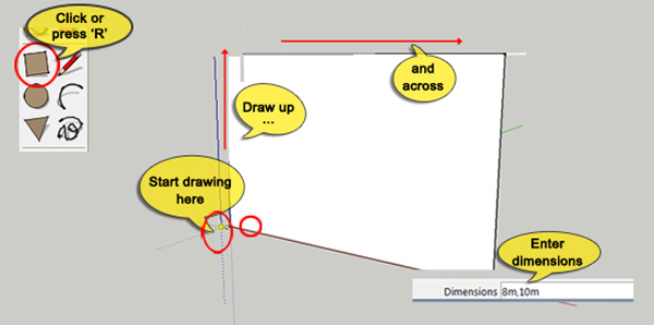
Click on the Rectangle tool in the toolbar or press “R” on the keyboard. Position the cursor where the 3 axes converge until you see the word “origin” appear. Hold down the left mouse button and draw up along the blue line (the up or z-axis), Then draw along the red line (the across or x-axis), making sure not to stray from the red line. You’ll see a rectangle appearing. Without clicking anywhere, type “8m,10m”. The measurements appear in the bottom right corner of the screen as you type. Press Enter and a rectangle of 8 meters wide and 10 meters high is created.
The figure (which is called ‘Susan’ by the way) has vanished but we’ll sort that out later.
Step 4
Zoom out and pan the view with the middle mouse button as indicated on the Quick Reference Card, so that you can see the whole rectangle you just created.
Select the Push-Pull tool or press “P”. Click on the rectangle and pull towards the horizon. Type “10m” and press Enter. Take care not to forget the “m”, otherwise Sketchup thinks you mean millimeters instead of meters. The rectangle has now become a box of 8 meters wide, 10 meters high and 10 meters deep.

Press the spacebar to activate the Selection tool. Click on the front face of the box so it becomes selected. Press “Delete” to get rid of it.

Step 5
At the moment the structure is nothing more than a box. Let’s do something about it by creating the roof. Activate the Line tool by clicking on its icon in the toolbar or by pressing “L”. Next go to the Top view by clicking on its icon in the View toolbar. Zoom out so that you can see the whole top rectangle. Hover the mouse over the top edge until you see a cyan circle, click and drag down to the bottom edge. Move the mouse over the bottom edge until another cyan circle appears, when it does, click to create a straight line.

Switch to the front view by clicking on its icon in the View toolbar. Hit the Spacebar to activate the Selection tool. Click on the line you’ve just created to select it. The line will turn blue. Press “M” or click on the Move tool icon in the toolbar. Hover the mouse over the selected line, click and drag it up along the blue axis. You’ll know when the Move tool is on the blue axis because a blue dotted line appears as you drag. Type “3m” to raise the roof 3 meters and press Enter to confirm.

The basic structure is now finished. Next we’ll create some details inside the building.
Step 6
The back wall will have the most detail, so we’ll start there. Position the camera so that you can see the whole of the back wall. Press the Spacebar to activate the Selection tool and select Susan, she’ll turn blue. Press “Delete” to get rid of her.
To make our lives easier, we’ll first create some guidelines on the back wall. Press “T” to activate the Tape Measure tool. Hover the mouse over the bottom edge of the back wall until a red square and the text “On Edge” appear. Click and drag up. Type “3.25m” and press Enter. You now have a horizontal guideline at a height of 3.25 meters.

Step 7
Activate the Rectangle tool (R) and hover the mouse over the point where the left edge of the back wall intersects with the guide line. As soon as you see a red cross and the text “Intersection”, click and drag diagonally to the bottom right corner of the back wall. When a green circle with the text “Endpoint” appears, click to create the rectangle.

Select the Push-Pull tool (P), click on the new rectangle and drag down to extrude it. Type “1.5m” and press Enter to complete the extrusion.

To tidy up, zoom out a little using the mouse wheel and actvate the Eraser tool (E). Click on the horizontal guideline outside the building to delete it. Do not try to click inside the building because that’ll erase parts of the building as well as the guide. It’s good practice to erase guidelines as soon as you’re done with them. If you don’t, the work area gets very messy very quickly and it becomes difficult to draw the shapes you need.

Step 8
To create the detail on the bottom half of the back wall, we need quite a lot of guidelines. Let’s start with the horizontal ones.
Starting at the bottom edge, create 2 new horizontal guides, using the Tape Measure tool (T) and the same method as in Step 6. Create a guide at 2.75m and another at 2m.

Next, create 6 vertical guidelines by dragging each one out from the left edge of the back wall, typing its position and pressing Enter. The positions are: 0.5m, 2.25m, 2.75m, 5.25m, 5.75m and 7.5m.

Step 9
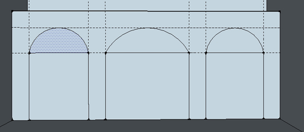
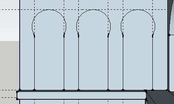
Activate the Rectangle tool (R) and draw 3 rectangles using the guidelines as shown below:

To turn the rectangles into arches, activate the Arc tool by pressing “A” or clicking on its icon in the toolbar. Hover with the mouse over the top left point of the first rectangle until a green circle appears, then click. Move the cursor over to the right top corner of the rectangle and click again when you see a green circle. Drag the mouse up until the arc snaps to the top most horizontal guide. Click to finish.

Do the same for the other 2 rectangles to create 3 arches in total.
Step 10
The arches and the rectangles are still separate surfaces. To be able to work with them effectively each arch and its rectangle have to be combined. Activate the Eraser tool (E) and click on each dividing edge in turn. This creates 3 complete arches.

Select the Push-Pull tool (P). Click on the left arch and drag the cursor up to extrude the arch inwards. Type “0.5m” and press Enter to extrude the arch inwards by half a meter.

With the Push-Pull tool still active, double-click on the center arch. This extrudes the arch inwards by the last entered distance, which is 0.5m. To finish up, double-click on the right arch to extrude it as well.

Zoom out until you can see the whole building. Select the Eraser tool and delete all guidelines by clicking on them in turn. Make sure to click outside the building to avoid deleting any geometry. If all went well, your building now looks like this:

Step 11
To finish the back wall, we’ll create some detail in the top half. First we need to put in some guides.
Activate the Tape Measure tool (T). Starting from the left edge of the back wall, create 2 vertical guidelines, one at 0.75m and another at 7.25m.
Next, starting at the top edge of the row of arches, draw 2 horizontal guides, one at 3.75m and the last one at 6.3m.

Using the guides, create an arch on the top half of the back wall by drawing first with the Rectangle tool (R), then with the Arc tool (A) and finally use the Eraser tool (E) to transform the arch into one, continuous surface.

Activate the Push-Pull tool(P) and move it over the arch. Click and drag to the right to extrude the arch inwards. Type “2m” and press Enter.
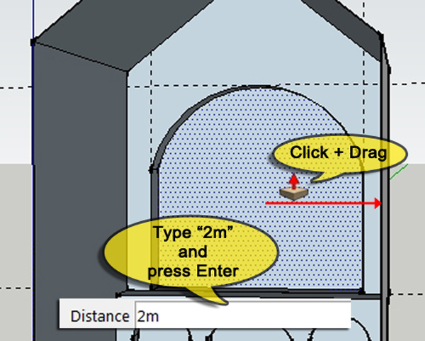
Use the Eraser tool (E) to erase all the guidelines.
The back wall is now finished. The left and right side wall are identical and we’ll create them using the same techniques which we’ve used up until now.
Step 12
Click the Right icon in the Views toolbar to switch to the right viewport. Right-click on the right side wall of the building and choose Hide from the popup menu to temporarily hide the wall. Zoom in/out until you have a good view of the left wall.

Select the Tape Measure tool (T), and, starting each at the left edge of the wall, draw 6 guides at the following positions: 1m, 3m, 4m, 6m, 7m and 9m.

With the Tape Measure tool still active, draw 4 horizontal guides, starting each at the bottom edge of the wall. The position are: 2.75m, 3.25m, 7m and 8.7m.

Step 13
Activate the Rectangle tool (R) and draw a rectangle using the 2 lowest horizontal guides.

Next, select the Push-Pull tool (P), position it on the rectangle you just created, click and pull down to extrude it outwards. Type 0.5 m and press Enter.

Step 14
Draw 3 arched windows using the same method as was used for the arches in the back. When you’re done the wall should look like this:
Activate the Push-Pull tool, click on the first window and drag to the right to extrude it outwards. Type “1m” and press Enter.

With the Push-Pull tool still active, double-click the remaining 2 windows to extrude them by the same amount.
Step 15
Press the Spacebar to activate the Selection tool. Click inside the first window to select the back face. Hold down Shift and click inside the other 2 windows so that all 3 back faces of windows are selected.

Press Delete to remove the faces so that the windows are open. You should be able to see the horizon line through them.

Step 16
Triple-click somewhere on the building to select everything. The building will turn blue. Next, right-click on the building and choose Unhide from the popup menu.
Use the Eraser tool (E) to delete all guidelines.

Step 17
Click on the Left icon in the Views toolbar to switch to the left view. Activate the Selection tool (Spacebar) and select and Shift-select all pieces belonging to the right wall. Right-click somewhere on the right wall and pick Hide from the popup menu to hide the right wall.
Draw horizontal and vertical guides with the same positions as indicated in Step 12. Next draw a ledge on the wall using the Rectangle tool (R) as in Step 13, followed by 3 windows, using the Rectangle tool (R) and the Arc tool (A) as shown in Step 14 and 15.


Triple-click somewhere on the building to select everything. Right-click on the building and choose Unhide from the popup menu.
We’re nearly done in Sketchup. The geometry is finished. All that’s left is to prepare the file for export to a file format that Photoshop can read.
Step 18
First we’ll sort out the lighting. Click on the Show/Hide Shadows icon in the Shadows toolbar to turn lighting on. Next, click on the Shadow Settings icon. When the dialog appears, enter the settings shown below. Close the Shadow Settings dialog.

Choose Window>Styles from the menu. In the dialog that appears, make sure Default Styles is the active style set and click on the second icon on the top row.

Step 19
Using the Orbit (O), Pan (H) and Zoom (Z) tools from the toolbar or your middle mouse button, position the camera so that the view in the viewport is close to that shown below. Don’t worry about getting it exactly right, just make sure the angle and size approximate the image.

Step 20
Last but not least, we’ll export the file. Choose File>Export>2D graphic from the menu and save the file as “Template.png”.

Part 2 Coming Soon…
This tutorial is too long to be published in it’s entirety (as it would take forever to load for you!).
Today we’ve walked you through the steps of creating a complex building structure in Sketchup.
This Friday look out for Part 2, where you will move over to Photoshop and learn how to turn this 3D structure into a realistic matte painting. It’s a beast of a tutorial so we’re sure you’ll enjoy it!
Member File Download
Download the original .psd file for this tutorial here:

 Members Area Tutorial: Create a Complex Alien Landscape Scene Using Matte Painting
 Members Area Tutorial: Create a Realistic Eye Shadow Case From Scratch in Photoshop
 Members Area Tutorial: Create a 3D, Textured Safe Illustration From Scratch Using Photoshop

Leave a comment
0 Comments:
No comments have been posted yet. Be the first!
Leave a Comment: